Here you can find the related products in Speedometer Sleeve Assy, we are professional manufacturer of Speedometer Specifications,Speedometer Shops,Speedometer Types.
We focused on international export product development, production and
sales. We have improved quality control processes of Speedometer Sleeve Assy to
ensure each export qualified product. Speedometer Specifications,Speedometer Shops,Speedometer Types,A Speedometer Indicates Guangzhou Taixin Auto parts Trading Co., Ltd. , https://www.hyundai-autopart.com
If you want to know more about
the products in Speedometer Sleeve Assy, please click the product details to view
parameters, models, pictures, prices and other information about Speedometer Specifications,Speedometer Shops.
Whatever you are a group or individual, we will do our best to
provide you with accurate and comprehensive message about Speedometer Sleeve Assy!
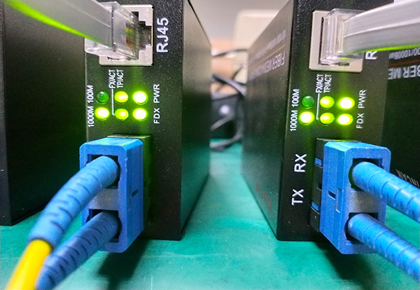
There are many types of optical transceivers, but the method of fault diagnosis is basically the same. Summarize the following faults that occur in optical transceivers:
1, Power light does not light power failure
2. If the Link light is not lit, the fault may be as follows:
1 Check if the fiber line is open.
2 Check if the fiber line loss is too large and exceed the receiving range of the device.
3 Check whether the fiber interface is connected accurately. The local TX is connected to the remote RX, and the remote TX is connected to the local RX.
4 Check whether the fiber connector is properly inserted into the device interface, whether the jumper type matches the device interface, whether the device type matches the fiber, and whether the device transmission length matches the distance.
3. If the circuit Link light is not lit, the fault may be as follows:
1 Check if the network cable is open
2 Check whether the connection type matches: devices such as network cards and routers use cross lines, and switches, hubs, etc. use straight-through lines.
3 Check if the device transmission rate matches.
4. The network is seriously damaged. The possible faults are as follows:
1 The electrical port of the transceiver is connected to the network device, or the duplex mode of the interface of the two devices does not match.
2 Twisted pair and RJ-45 head have problems and are tested.
3 fiber connection problem, whether the jumper is aligned with the device interface, whether the pigtail and jumper and coupler type are matched.
5, the fiber transceiver can not communicate after the two ends are connected
1 fiber is reversed, and the fiber is connected to TX and TR.
2 RJ45 interface is not properly connected to external devices (focus on straight-through and splicing)
The fiber interface (ceramic ferrule) does not match. This fault is mainly reflected in the 100M transceiver with photoelectric mutual control function. If the pigtail of the APC ferrule is connected to the transceiver of the PC ferrule, it will not be able to communicate normally. The photoelectric intercommunication transceiver has no effect.
6, time pass and break phenomenon
1 It may be that the optical path attenuation is too large. At this time, the optical power of the receiving end can be measured by the optical power meter. If it is within the range of receiving agility, the optical path fault can be basically judged within the range of 1-2 dB.
2 The switch connected to the transceiver may be faulty. In this case, the switch is replaced by a PC, that is, the two transceivers are directly connected to the PC, and the two ends are connected to PING. If the switch is not present, the switch may be basically determined to be a fault of the switch.
3 may be a transceiver failure. At this time, the transceiver can be connected to the PC at both ends (not through the switch). After both sides have no problem with PING, transfer a large file (100M) from one end to the other end and observe its speed. If the speed is very slow (files of less than 200M are transmitted for more than 15 minutes), the transceiver can be basically judged to be faulty.
7, after a period of communication, crash, that is, can not communicate, return to normal after restart
This phenomenon is generally caused by the switch. The switch performs CRC error detection and length check on all received data. It checks that the packet with the error will be discarded and the correct packet will be forwarded. However, some packets with errors in this process are not detected in the CRC error detection and length check. Such packets will not be sent during the forwarding process and will not be discarded. They will accumulate in the dynamic cache ( Buffer), can never be sent out, wait until the buffer is full, it will cause the switch to crash. Because restarting the transceiver or restarting the switch at this time can restore the communication to normal, the user usually thinks it is a problem with the transceiver.
8, transceiver test method
If you find that there is a problem with the transceiver connection, please test it as follows to find out the cause of the failure.
1 near-end test
Both ends of the computer to PING, if you can PING通, then confirm that the fiber transceiver is no problem, such as the near-end test can not communicate can be judged as the fiber transceiver failure.
2 remote test
If the computer at both ends is not connected to PING, if the PING is unreachable, it must check whether the optical path connection is normal and whether the transmitting and receiving power of the optical transceiver is within the agreed range. If PING is passed, it proves that the optical path is connected properly. You can determine the fault problem on the switch.
3 remote test to determine the point of failure
First connect one end to the switch, and both ends to PING. If there is no end fault, it can be judged as failure of another switch.
May 17, 2023