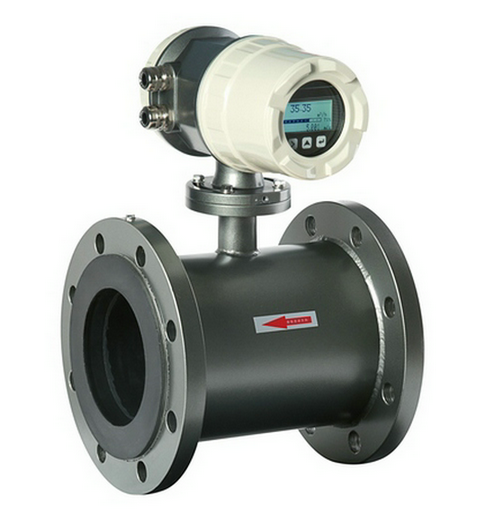
Electromagnetic flowmeter installation and common faults I. Introduction Electromagnetic flowmeter in the use of common failures, some because of the failure of the instrument itself caused by damage, and some due to improper use, improper installation, environmental conditions, fluid characteristics and other factors caused by the failure, such as display fluctuations, precision decline or even instrument damage . It can generally be divided into two types: failures during installation and commissioning (faults during commissioning) and failures during normal operations (operational failures). Second, debugging failure Debugging and expecting faults generally appear in the instrument installation and commissioning stage. Once they are eliminated, they will not appear again under the same conditions. Common debug-time faults are usually caused by improper installation, environmental interference, and fluid characteristics. 1) The installation is usually caused by the incorrect installation position of the electromagnetic flow sensor. Commonly, such as installing the sensor at the highest point of the pipe system that can easily accumulate gas, or installing it on the vertical pipe from top to bottom, the emptying may occur; Or there is no back pressure behind the sensor and the fluid is directly discharged into the atmosphere to form a non-full tube inside the measuring tube. 2) The environment is usually dominated by stray currents in the pipeline, strong electromagnetic interference in the space, and magnetic interference in large electrical machines. Pipeline stray current interference usually achieves satisfactory results with good individual ground protection, but in the case of strong stray currents (such as the electrolytic shop pipe, sometimes the peak potential of the AC potential induced at the two electrodes can be as high as 1V), Additional measures must be taken to insulate the flow sensor from the pipeline. Space electromagnetic interference is generally introduced via signal cables and is usually protected by single or multi-layer shielding. 3) Fluids The measured liquid contains evenly distributed microbubbles that usually do not affect the normal operation of the electromagnetic flowmeter. However, as the air bubbles increase, the output signal of the instrument fluctuates. If the bubbles are large enough to cover the entire surface of the electrode, As the bubble flows through the electrode, the electrode circuit will momentarily open and cause greater fluctuations in the output signal. Third, the operating period failure Run-time failure is a failure that occurs after the electromagnetic flowmeter has been commissioned and operated for a period of time. Common operational failures are caused by factors such as the adherence of the inner wall of the flow sensor, lightning strikes, and changes in environmental conditions. 1) Adhesion layer on the inner wall of the sensor Since electromagnetic fluid flow meters are commonly used to measure dirty fluids, after a certain period of operation, they often accumulate adhesive layers on the inner wall of the sensor and cause failures. These faults are often caused by too much or too little conductivity of the adhesion layer. If the attachment is an insulating layer, the electrode circuit will be open circuit, the meter can not work properly; if the adhesion layer conductivity is significantly higher than the fluid conductivity, the electrode circuit will appear short circuit, the instrument can not work properly. Therefore, the adhered scale layer in the measuring tube of the electromagnetic flowmeter should be promptly removed. 3) Changes in environmental conditions During commissioning, the meter is working properly because the environmental conditions are still good (for example, if there is no interference source), and it is often easy to neglect the installation conditions (for example, the grounding is not very good). In this case, once the environmental conditions change, new sources of interference occur during operation (such as welding on pipelines near the flowmeter, large transformers installed nearby, etc.), which will interfere with the normal operation of the meter, and the output of the flowmeter. The signal will fluctuate
Tubular heat exchanger is a wall heat exchanger with the wall surface of the tube bundle enclosed in the shell as the heat transfer surface. The heat exchanger has the advantages of simple structure, low cost, wide circulation section and easy cleaning of scale. However, the heat transfer coefficient is low and the floor area is large. It can be made of various structural materials (mainly metal materials) and can be used at high temperature and high pressure, which is the most widely used type.
It is a wall heat exchanger with the wall surface of the tube bundle enclosed in the shell as the heat transfer surface. The heat exchanger has the advantages of simple structure, low cost, wide circulation section and easy cleaning of scale. However, the heat transfer coefficient is low and the floor area is large. It can be made of various structural materials (mainly metal materials) and can be used at high temperature and high pressure, which is the most widely used type.
This kind of heat exchanger has a large heat transfer area and can work at a lower temperature and is welcomed by people, so its application field is very wide. Tubular Heat Exchanger,Pool Shell And Tube Heat Exchanger,Tubular Plate Heat Exchanger,Pool Shell Heat Exchanger Jiangsu Baode Heat-Exchanger Equipment Co.,LTD , https://www.baodeexchanger.com
When the low-frequency square-wave excitation electromagnetic flowmeter measures excessive solid content slurry, it will also produce slurry noise, causing the output signal to fluctuate.
When measuring mixed media, if you enter the flow sensor for measurement before the mixing is not uniform, the output signal will also fluctuate.
Improper matching of electrode material and measured medium will also affect normal measurement due to chemical action or polarization. The electrode material should be properly selected according to the instrument selection or related manuals.
2) Lightning Strikes Lightning strikes can easily induce high voltages and surge currents in the instrument lines, causing damage to the instrument. It is mainly introduced through the power line or the excitation coil or the flow signal line between the sensor and the converter, and is particularly introduced from the power cable of the control room. 
October 26, 2024