At present, the use of electric bills and three-phase hybrids for equipment and equipment in our military equipment is relatively common. Ordinary single-phase or three-phase alternators cannot meet the needs well. Single-camera groups cannot supply power to three-phase equipment. The single-phase load capacity of the three-phase unit is poor, and in the case of a large amount of three-phase load imbalance, the three-phase voltage is also extremely unbalanced, which seriously threatens the safe use of the power equipment and the generator set. In order to meet the special needs of the troops, we designed a single-phase and three-phase gasoline generator to assemble a gasoline generator set, which satisfies the requirements of single and three-phase mixed use of the troops, and minimizes the imbalance of the three-phase voltage, so that each use Electrical appliances can be used safely and reliably. The following is an introduction to the design of various performance indicators of 8kW single and three-phase generator sets that have been technically certified. Working principle According to the special needs of single and three-phase AC synchronous generators, we adopt a reactive shunt excitation method with good performance and simple structure, and its electrical schematic diagram is as follows. Single and three-phase AC synchronous generator electrical schematic diagram The generator stator is embedded with a set of main windings, a set of secondary windings, the main winding outputs three-phase AC power and single-phase AC power, and the tail ends of each phase winding are respectively separated from the three-phase shunt The middle tap of the reactor is connected with M phase, the first end is the output end, the first end of the auxiliary winding is respectively connected with one end d of the reactor, the tail end is connected with the three-phase rectifier bridge, the phase of each phase of the reactor is another. The end d2 is connected together to become the midpoint and the out-of-synchronous generator is in no-load. When the rotational speed reaches the rated value, due to the residual magnetism in the rotor, a voltage is induced in the secondary winding and excitation is provided to the rotor excitation winding. The current 4 (voltage component) increases the magnetic flux. If this continues, the motor can be self-excited and the no-load voltage is quickly established. When the load is applied, the load current of the reactor is shunted, and a part of the current becomes the excitation current //i (current component) of the steering excitation winding, compensating for the demagnetization and voltage drop when the generator is loaded, so that the excitation current of the rotor changes with the load. And automatic adjustment, to achieve the role of constant terminal voltage. The design and calculation of single and three-phase AC synchronous generators are the same as those of the alternating current synchronous generators, but it should be noted that the coordination of single and three-phase parameters and the balance of performance indicators are required. Therefore, the following points should be noted. Since the motor is mainly used with the square cabin, it has strict requirements on its volume and weight. Therefore, the stator winding design of the motor must be arranged reasonably. In a limited space, the motor output is maximized, and the phase and phase are The mutual inductance is small to reduce the amount of three-phase voltage imbalance during operation. The simplest and straightforward method is to design the single-phase and three-phase windings into two independent windings. However, this will inevitably increase the volume and weight of the motor, and the operation is also cumbersome during operation, and it is impossible to achieve single-phase and three-phase mixing. The ideal solution is to design one of the phases to output the same power single-phase winding on the basis of the three-phase generator, so that the phase is subjected to the single-phase load, which saves the material and conforms to the actual use. We used two options during the design process. Option 1: See the generator winding system. The stator coil is provided with two sets of phase windings, one set is connected to three phases as a three-phase winding, and the other is connected in series to form a single-phase and three-phase winding with a smaller number of turns. This is a conventional winding arrangement. After trial production and related tests, it is found that there are two shortcomings. One is that since the single-phase winding has some coils and the other two phases are in the same phase space, the motor has a large mutual inductance when operating. Secondly, The weaving process is complicated, and there are 4 kinds of windings embedded in some slots. The absolute phase 1 marks the U phase V phase W phase the primary side number 584858 negative side number 196153196 Table 2 measured standard excellent product electricity / industrial steady state consistency three cups" 2. Option 2: See the generator winding system. The stator coil is only provided with one set of three-phase windings, and one of the phase windings is wound twice as many times as the other two phases, and is used as a single-phase winding. In this way, the winding arrangement is relatively neat and regular. Since the single-phase winding and the other two phases are in the same phase in space, the mutual inductance coefficient is small, and when the generator is unbalanced, the three-phase voltage unbalance is small. The winding is completely the same as the three-phase AC synchronous generator except for the number of windings of one phase. The embedded wiring process is simple, and the insulation is easy to handle. Compared with the scheme 1, the copper material can be saved by about 15%, and the slot of the slot is partially The full rate can be reduced by about 10%, and the program is proved to be ideal. The generator adopts the reactive shunt excitation mode. The system has simple structure and excellent performance, but the rectification coefficient and armature reaction of the bridge group are different when the single-phase and three-phase operation of the motor are different, such as full pressing. For three-phase design, the excitation power is not enough when single-phase operation; if the three-phase standby operation is completely in accordance with the single-phase design, the resistance load voltage is too high, and coordinated balancing measures must be taken. The method we adopt is to design the reactor as an unbalanced reactor. The winding parameters on both sides of the reactor are designed according to the three-phase motor, and the middle phase winding is designed as a single phase, which satisfies the requirements of single and three-phase generators. When the motor is unbalanced, the voltage imbalance is small. The specific data is shown in Table 1. In order to enhance the motor process adaptability, improve the motor voltage regulation accuracy, and reduce the voltage cold and hot state deviation, we add an automatic voltage regulator in the excitation system. Since the motor needs single and three-phase operation, the measurement is performed. The signal can only take the single-phase phase voltage, and the single-phase voltage harmonic content is more (including the sub-harmonic), especially in the single-phase operation, which makes the regulator's voltage regulation accuracy not high, generally only 7%. ~10%, can not meet the technical requirements, must increase the compensation device. However, due to the large current variation during single and three-phase operation, it is not suitable to use the load current as the feedback signal. Only the motor excitation voltage can be used as the feedback signal. In the single-phase voltage regulator measurement circuit, a reflection excitation voltage is added. The feedback signal, using optocoupler isolation, meets the requirements, as seen on its specific line. The prototype passed the cold zone, hot zone, reliability and force use test, and the quality inspection by the National Internal Combustion Engine Power Station showed that all performance indicators met the design requirements. The specific indicators and quality scores are shown in Table 2. Single and three-phase The gasoline generator set can output single and three-phase alternating current separately, and can output single and three-phase alternating current at the same time. The use of single and three-phase hybrids for electrical equipment not only exists in the military, but also exists in civilian sites such as construction sites. Its development has been successful, filling the domestic gap and having extensive promotion value. Currently, it has been used for engineering vehicles and other products. More than 500 sets, its unique features, greatly meet the needs of the use of the troops, welcomed by the use of troops.
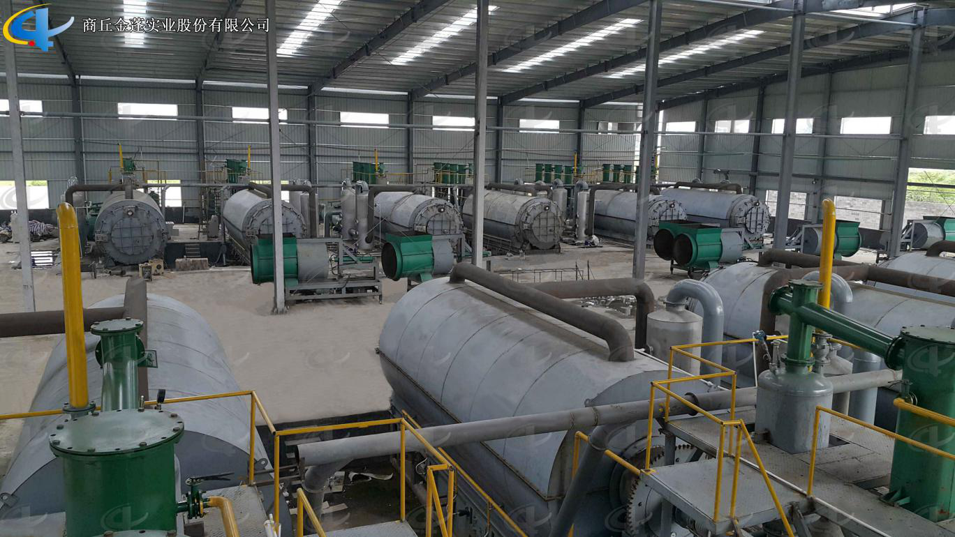
Batch Waste Tyre Pyrolysis Plant
Pyrolysis Plant is used for recycling waste tire, waste plastic, waste rubber to fuel oil. According to the actual situation in every country and district, we developed different models of Batch Pyrolysis Plants for waste tires, rubber and plastic with daily capacity 5 -10 tons.
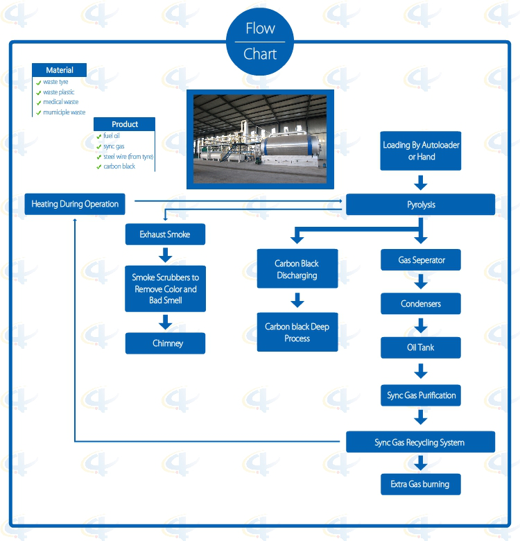
Flowchat of Batch Waste Tyre Pyrolysis Plant
Advantages of Batch Waste Tyre Pyrolysis Plant
1. Full open door design: Speedy loading in and steel pulling out; Easily cooling down after one batch finished, saving time; No leaking with special high temperature flexible graphite packing.
2. Unique Craft Condensers: High condensing efficiency with more oil output. Good quality oil, longer lifetime, and easy to clean.
3. National Patent Unique Smoke Scrubbers: More efficient removal of the acid gas and dust of the smoke by neutralization, purification and absorption, environmental friendly without pollution.
4. National Patent Carbon Black Discharging System: Speedy fully enclosed Auto-discharging under high temperature, avoiding carbon black pollution, saving time.
5. Automatic Submerged welding technology, ultrasonic nondestructive testing, both manual and the automatic safety devices.
6. Sync Gas Recycling System: Fully burned after recycling and utilization, saving fuel and preventing pollution.
7. Direct Heating System: Enlarging heating square to lengthen the lifespan of the reactor and easy to control the temperature.
8. National Patent, unique heat insulation shell; high efficiency temperature keeping, excellent energy-saving effect.
Technical Parameter of Batch Waste Tyre Pyrolysis Plant
NO.
ITEM
PROJECT
1
Equipment Model
XY-7
XY-8
2
Door Model
Full Open Door
Full Open Door
3
Suitable Raw Materials
Rubber/Plastic Products
Rubber/Plastic Products
4
Structure
Horizontal Type Revolves
Horizontal Type Revolves
5
Reactor Size
Φ2200*6000mm Φ2600*6600mm
Φ2200*6000mm Φ2600*6600mm
6
Capacity for One Batch
5-6Mt; 8-10Mt
5-6Mt; 8-10Mt
7
Oil Yield of Tires
40%-45%
40%-45%
8
Work Pressure
Normal Pressure
Normal Pressure
9
Reactor Rotation Speed
0.4R/M
0.4R/M
10
Fuels Choice
Coal, Wood
Coal, Wood, Gas, Oil
11
Power
18KW/H
18-25KW/H
12
Cooling Method
Water Cycling
Water Cycling
13
Type of Drive
External Annular Gear
External Annular Gear
14
Heating Method
Direct
Direct
15
Type of Installation
With Foundation
With Foundation/Integrated Base
16
Noise dB(A)
≦85
≦85
17
Operation Mode
Intermittent Operation
Intermittent Operation
18
Total Weight(MT)
25-40
25-40
19
Installation Space Required
30m*10m
30m*10m
20
Manpower
3~4/batch
3~4/batch
21
Shipment
Ф2200×6000=1*40HC+1*40FR
Ф2600×6600=2*40HC+1*40FR
Ф2200×6000=1*40HC+1*40FR
Ф2600×6600=2*40HC+1*40FR
Batch Waste Tyre Pyrolysis Plant Batch Waste Tyre Pyrolysis Plant,Waste Tyre Pyrolysis Plant,Rubber Pyrolysis Recycling Plant Shangqiu Jinpeng Industrial Co., Ltd. , https://www.recyclingthewaste.com

August 27, 2019